
The first contribution is about The Neckermann 150 in 1 project kit.
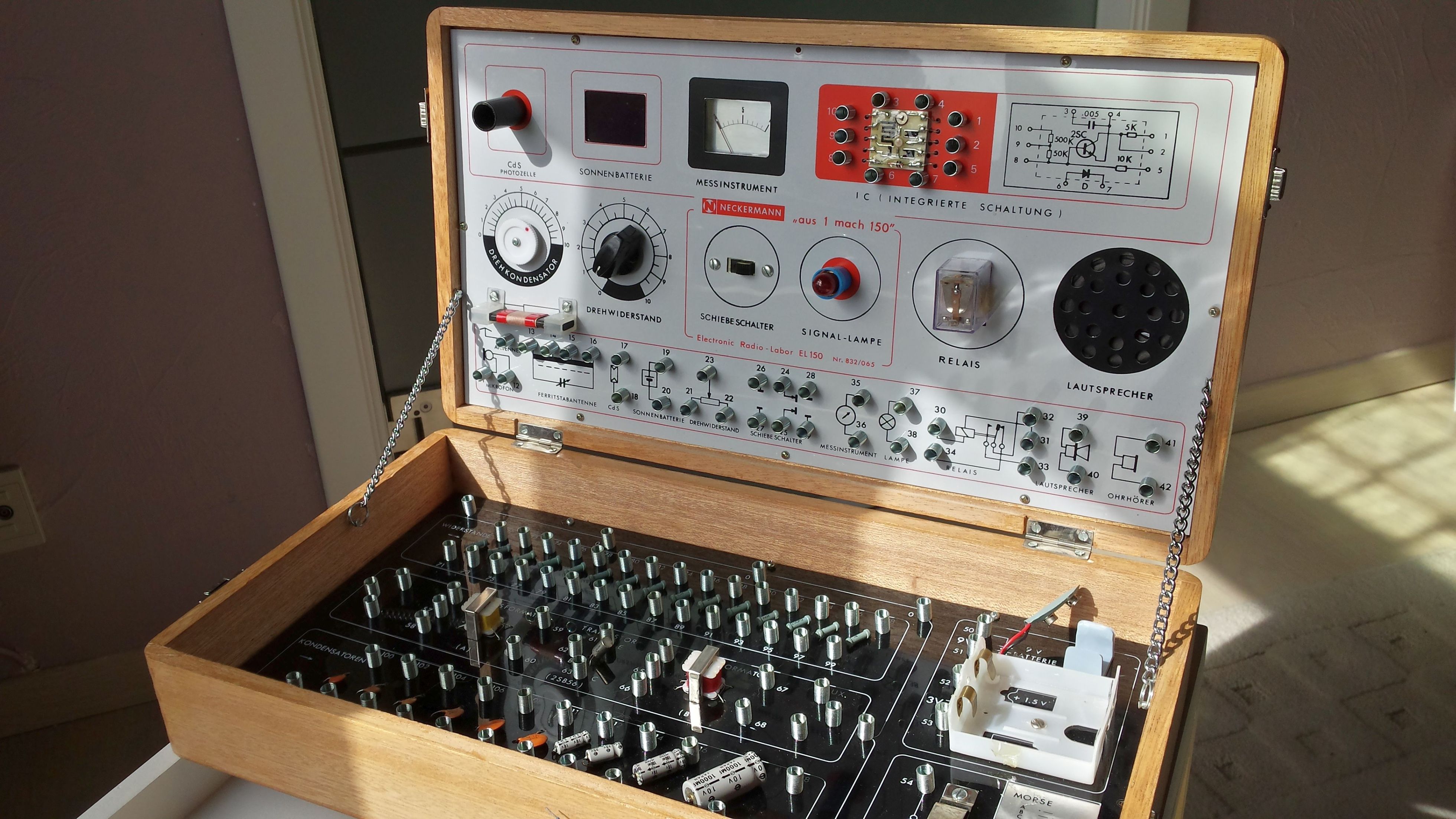
This kit came in a nice wooden case with locks on both sides. When opening the lid, chains on both sides hold the top lid. Very nice.
This kit was also distributed by Gakken and Lafayette.
It has plenty of fun electronic stuff inside, Lots of resistors, transistors, radio circuits,solar cell, integrated circuit and many more.
Since the manual lacks detailed information about the circuits, I decided to rewrite this manual and make many improvements to the circuits. Even new unpublished circuits will be handled here. I will also include measurements and formulas so you will be able to gain better understanding of the circuits.
Have fun
A reflex radio : a very sensitive AM radio.

I loved this kit as a child.
There was one circuit that I couldn’t quite work out. It was the voice changing circuit.
I wish I could find an online copy of this great instruction booklet.
Thanks for bringing back some good childhood memories…
LikeLiked by 1 person
Hi there !
Glad you like this neat electronic kit !
I have almost finished rewriting the original manual.
In the original manual, most circuits were badly designed and could be improved.
I have also added more experiments and redesigned the original circuits so that they perform better.
New circuits include games, basic electronics, sound sculpting devices, astilbe multivibrators, thyristor and many more.
I haven’t yet tried the voice changing device but certainly will have a look at it.
Do you still have this experiment set ?
Greetings
LikeLiked by 1 person
Hi Frank,
Apologies for the delayed response.
Yes, I sure do! It’s in fairly good shape. I think the solar panel and volt meter have gone into some other project years ago.
I thought I had the manual but I can seem to find it at the moment.
That’s why I was pleasantly surprised to see it posted here. Albeit in German. I can say from memory that the English version I had must have been translated directly from German.
My version’s dialogue was very querky. All the pictures were the same.
I would love to see some of your new circuit designs especially an English version. Of course I must complete the voice changer circuit. The only one out of the entire book I never got working.
Keep up the good work.
Eddie
LikeLike
Actually, I was just looking at mine. It is very subtly different in physical layout. Is there some way or another to get you a picture of mine?
LikeLike
Hi Eddie,
Sorry for late reply, so many things I had to handle the last months …
The Lafayette kit has indeed a differnet layout but the numbered spring connections are the same.
Also the text is in English and not in German.
Lately, I picked up this kit again and made a very good selective and sensitive MW radio.
I will publish new circuits and this radio very soon.
I hope you find the meter (maybe from auction sites) since this is a vital component for measuring, outputting signals etc.
I use it extensively in almost every circuit to demonstrate the flow of electricity.
many greetings,
Frank
LikeLike
I have one of these – back in 1972 it was a Christmas present and later I entered a career in electronics.I no longer have the instruction book, I don’t suppose anyone has a copy they can scan? Happy to cover costs
LikeLike
Hi Tony,
I have the German version of the Neckermann kit (it is the same as the Lafayette).
The only problem is that the original experiments lack creativity and are too simple and somewhat look alike.
Some experiments are even bad in design so that components can be destructed and most of those parts are impossible to get.
This is why I started this website with fresh updated diagrams and lots of explanation what and why is happening.
You can see this as a new manual. Every circuit has been tested thoroughly.
Many new circuits, missing in the original manual, have been introduced like flip flops, Schmitt triggers, games, etc.
From time to time I will add more content to the website as time permits.
Hopefully you’ll enjoy.
Many greetings
LikeLike
Hi Frank and Tony,
I hope you are both well.
I love the updated site. I must look into trying out your new circuit designs.
By the way as luck would have it I just now found online somebody who has a scanned copy of the original English version manual here……
https://bama.edebris.com/manuals/lafayett/150-1/
It’s the same one I had.
I found a picture of the kit I have.
https://www.radiomuseum.org/r/lafayette_150_in_1_electronic_kit.html
Notice the top cove layout is slightly different.
As luck would have it a finally got some spare time to look into the circuit that I could never quite get to work as a child.
It is expriment number 89 “Talking Sound” experiments (in both the English and German manual versions).
I put an old oscilloscope on the circuit. It turns out that the circuit indeed works fine as intended.
I believe the issue lies in not enough audio to drive the circuit. I used a smartphoine output thru a cutoff headphone jack to get the desired audio output. it is not a great amount. However the carbon microphone in the kit doesn’t seem to be enough to excite the circuit. Which is why I probably couldn’t get it work as a child.
Changing the 2k Ohm resistor to a smaller one helps as well. i substituted the 2k Ohm one for the lower one next to it (connections 78 & 79 instead of 80 & 81).
I hope this helps someone.
Take care,
Eddie.
LikeLike
Hi !
Thank you for the link to te English manual, this can come very handy for fellow enthousiasts.
The Lafayette and Neckermann kits are in fact derivates from the original Gakken in kit.
Neckermann was aimed at the German market and Lafayette to the British market.
The spring numbers are completely the same but the parts were differently located.
I encourage everybody to protect the IC from damage.
All you have to do is to disconnect the Collector and Emitter leads of the 2SC transistor, the diode, the 5k resistor and the 0.005 µF capacitor.
Mount a 2N3704 transistor, a Ge diode, a 5k resistor and a small disc capacitor of 0.0056 µF behind the white panel.
I made several tests and the circuits work perfect !
Now about your experiment, i will surely have a look at it.
This experiment seems interesting to try it out !
Recently I designed a reflex radio with this kit.
It’s so sensitive that with only a 3m wire, used as antenna, I can pick up about 10 radio stations in the evening.
Some are so loud that the speaker produces enough volume to fill the room with music !
I will try to post a picture here in a new topic.
Many greetings and much fun with your electronic kit,
Frank
LikeLike
Hi Frank,
My pleasure. I do hope this helps someone out. I certainly know this site helped me out a heap. Thank you!
Very interesting information about the 3 variants of kit. Somehow Gakken rings a bell. I have had a good look at my kit and there’s the name under the speaker to the right of the kit that says Gakken. Is it Japanese? I live in Australia.
You’ve inspired me to replace the missing components I pinched from the kit many years ago. I think I can replace them all.
With the magnetic meter, I will have to buy a new one. Would you be kind enough to let me know what type of meter I should be looking for? I imagine that it will be some kind of micro ammeter. I am not sure though. Any insights will help.
Many years ago I burned out the IC chip transistor. I did replace it like you have suggested by discreetly mounting it to the back out of sight. However it was whatever I had laying around at the time. I will change it out for the out for the one you recommend when I do the other remedial work.
Just a thought maybe you could have these manuals here on your site incase these other sites go down. It would be nice to have a way to upload images and other things as well.
Many thanks again. A great site!
Keep up the good work.
Eddie.
LikeLike
Hi there !
I will make a copy of the manual and will make a link to it on this website.
But be aware that many circuits are badly designed and sometimes wrong.
This could be also the reason why the voice changing circuit didn’t work.
You may perhaps have noticed that i posted one of my more complicated circuits here : an AM reflex radio.
When i’ll find more time, I will continue to publish more circuits.
About the meter, look out for any Gakken or Science Fair electronic kit of the same era on auction sites.
The meter in those kits are a perfect replacement.
I also did many experiments to find a suitable replacement for the 2SC transistor, the 2N3904 is perfect (any other failed in radio circuits), so be sure to have this transistor installed !
Many greetings
LikeLike
Hi Frank,
Thanks for keeping a repository for this electronic kit alive.
I agree, I think the reason for the failed IC chip transistor was a bad experience I had with an example from the original manual. It happened many many years ago when I first got the kit as a child. There is not a good amount of detail to the operations in the original documentation.
I do very much like the new circuit experiments you have created. It is very helpful to have an in-depth analysis of the circuit experiments as well.
I did see the AM radio circuit experiment. I will have a go at it. It looks good.
I do like the explanations you have for the basic circuit experiments. It helps to explain what is happening in the circuit. To be honest it is so important to have a solid grasp of the fundamentals of electrical theory.
I’ll get the 2N3904 transistor you suggest for a replacement for the IC chip transistor.
I need to get a solar cell. I believe the dimensions should be 3 X 2.5cm (30x25mm) or maybe just a bit more so it doesn’t fall thru the panel hole. I vaguely remember that the original solar cell was constructed on a metal backing plate.
If I don’t have any luck sourcing an original micro ammeter, are there any electrical specifications I should be looking for in a new one. Such as maximum current/voltage?
Is there a way to upload images in the comments section?
Thank you for your time in responding to my questions.
Take care.
Eddie.
LikeLike